My Bike Speedometer is 60 times more accurate than yours
There are four linked posts in this set:
- The actual setup of the bike and gaming equipment
- Problems with Cadence Sensors
- Making a much more effective speed/cadence sensor (this post)
- Using the sensor as an input for video games
A consumer bike speed detector knows when a wheel has made a complete rotation and it will use Bluetooth to send that information. If you stop (or start) suddenly, the controller for the sensors can be sure you have stopped about three seconds later.² My notes (and complaints) on working with a consumer sensor are here.
I built my own speedometer that detects every time the wheel moves 1/60th of a rotation. It can tell you an accurate cadence reading with just 0.30 seconds worth of data and the controller knows a complete stop (or start) has happened within 0.1 seconds.³
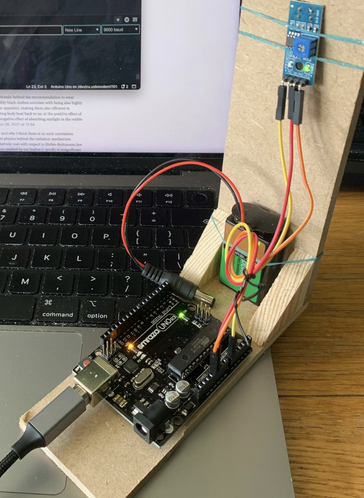
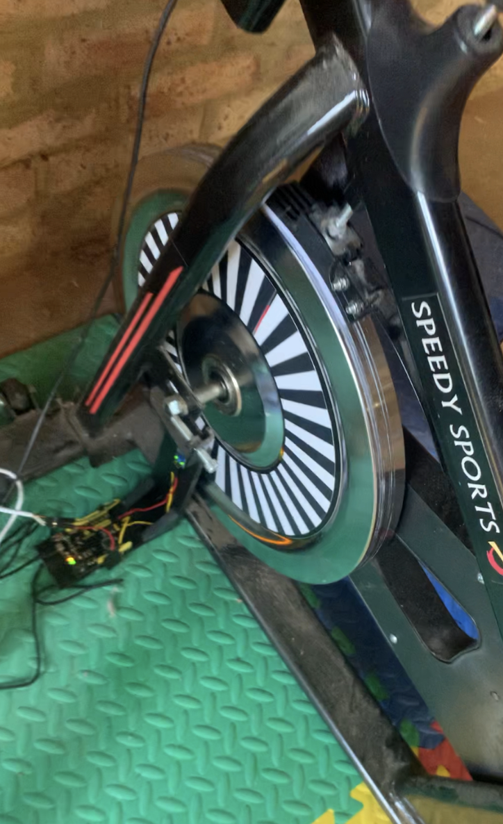
Here is the sensor:
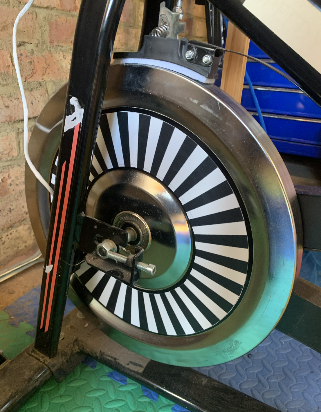
Which I am extremely proud of. It works because I’ve put an alternating pattern of 60 black and white segments onto the wheel. You can see the setup here:
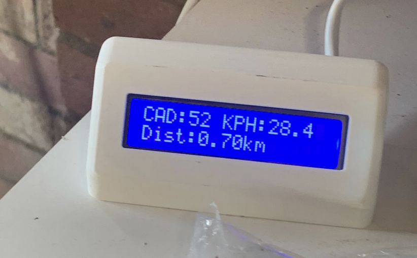
The sensor sends data to an Arduino which works out the values to display (currently cadence, speed, and distance, even if two of these are arbitrary on a spin bike) on this unit that we have on the desk:
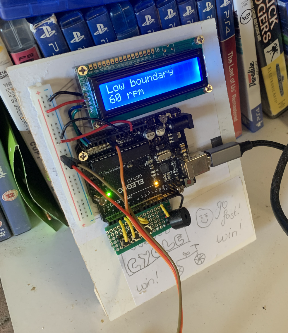
The display unit is ugly but will get a housing shortly. Those buttons adjust the mode (is the alarm on? is it currently controlling a computer game?), and the alarm boundaries (I have it set to trigger the alarm when cadence drops below 60).
I had to learn (and re-learn) an awful lot for this project. Before I started I didn’t know anything about 3D printing (the sensor cover and the display cover are both 3D printed designs), soldering (all the wires on the display), or even what crimping was (it’s getting wires the right size and using odd tools to lock them into holders). I didn’t know anything about an Arduino other than I could make it blink an LED at me and all my electronics was roughly remembered teenage taking-things-apart. I did at least know the maths and the C++ one needs to program an Arduino, but everything else has been a serious upskilling.
Parts list
| Item | Price | Quantity Bought | Quantity Needed |
|---|---|---|---|
| Arduino Leonardo | £11.99 | 1 | 1 |
| I2C IIC LCD 1602 Module | £10.95 | 2 | 1 |
| TCRT5000 IR Reflective Sensor | £8.99 | 10 | 1 |
| Magnetic segment pattern printing | £20.00 | 1 | 1 |
| Total | £51.93 |
This parts list is now hilariously out of date because I keep buying all manner of wires and tools and stripping down old things and then buying things on the off chance. Right now it’s missing buttons, a speaker, and some perfboard but…
History
I considered two designs:
- Lots of magnets around the rim and a hall effect sensor that pings every time a magnet passes.⁰
- Measuring the voltage of a dynamo attached to the wheel.
However, some guy online suggested I use an optical sensor because my flywheel has eight coloured segments.
I did a proof of concept test with a photoresistor. It worked well enough that I was willing to buy some of these IR sensors, which I ordered on the 4th March 2025 because I understood they would be a bit more accurate and effective.
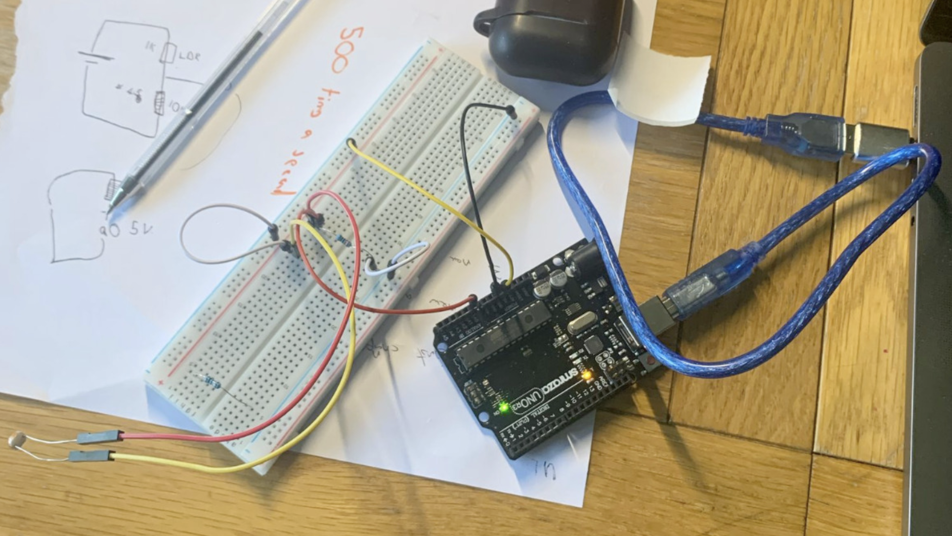
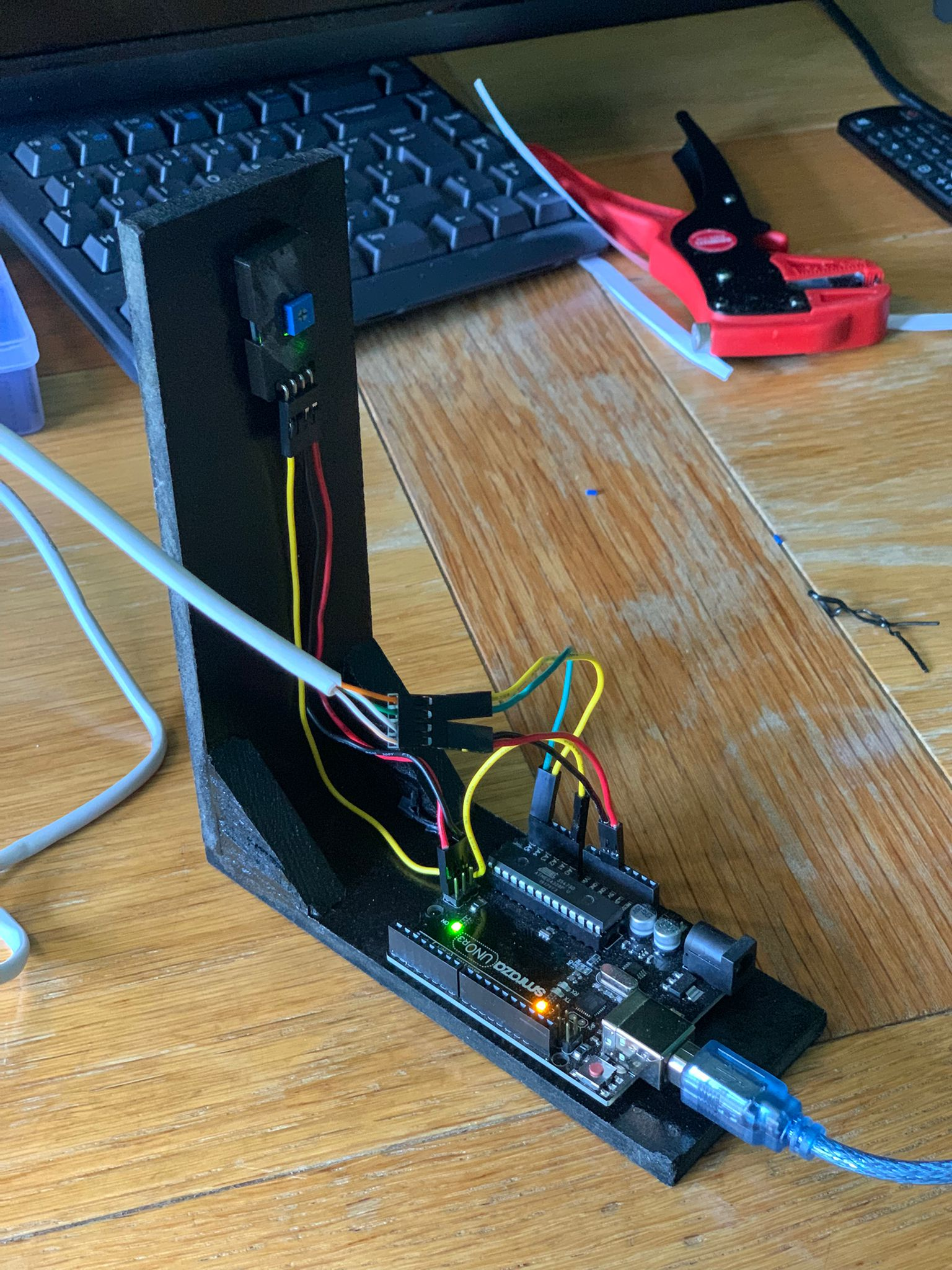
I made a simple stand out of scrap wood in the garage¹ and built this:
…and tested it on my bike setup
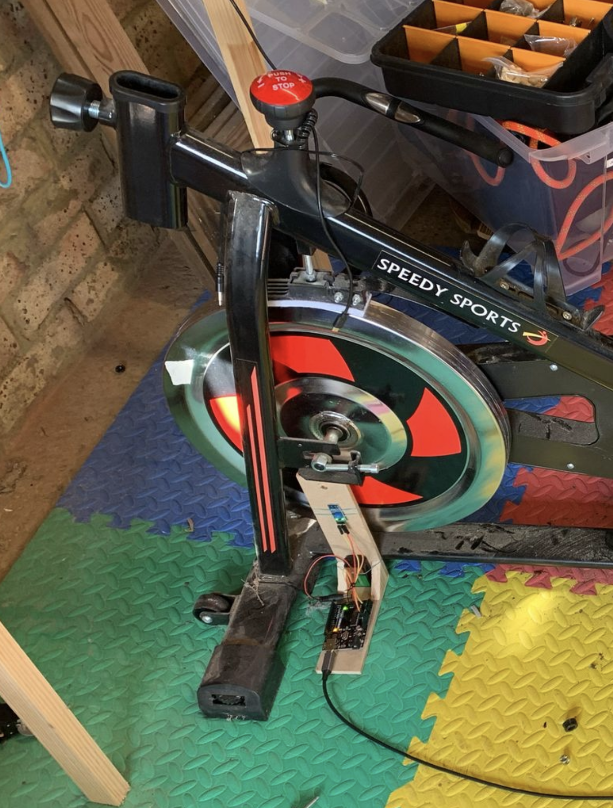
My test pilot got it up to 7.5 rotations per second so was functioning. It registered the speed accurately at low speeds, which a consumer system doesn’t do and detects acceleration and deceleration much earlier.
Version 2 (June 2025)
I took it apart and spray painted the stand.

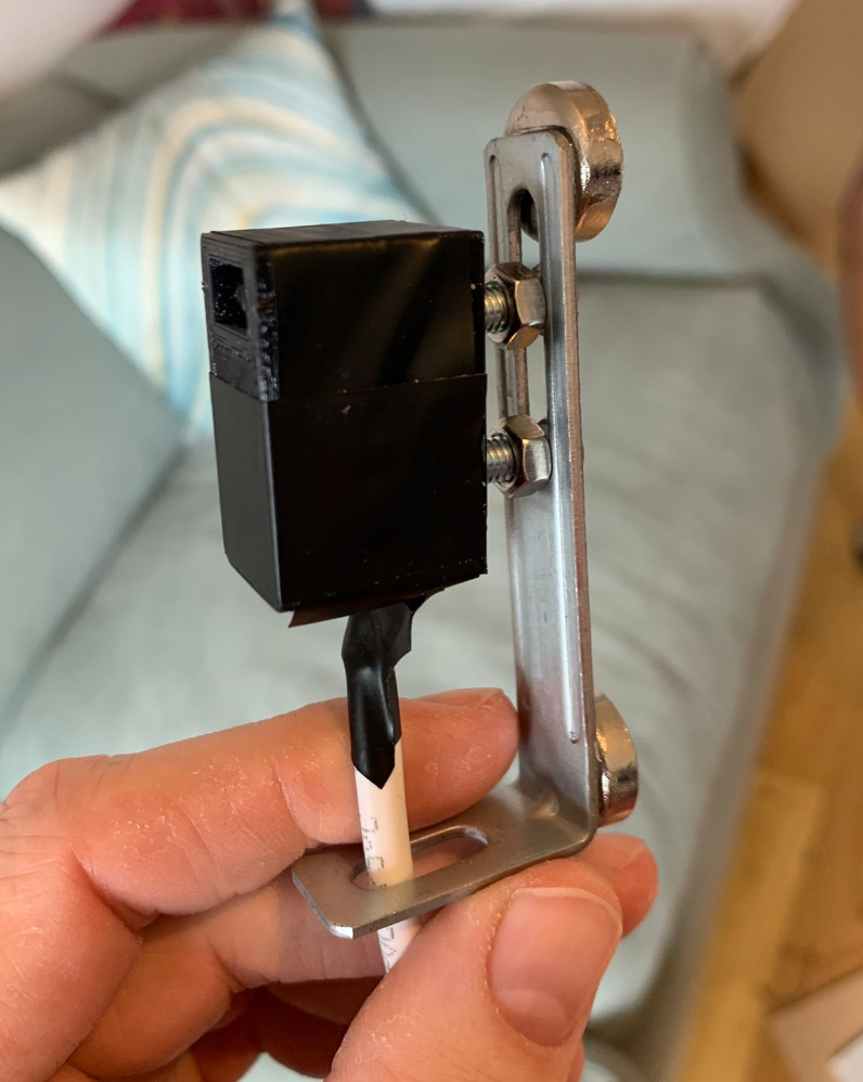
I refitted the IR sensor, screwed it on properly rather than using an elastic band, and then 3D printed a simple cover for it. I bought myself a crimping kit and tidied up all the wires:
The previous version required the laptop there all the time. That was fine for me but my partner is training for a triathlon. I 3D printed a housing for an LCD display and worked out how to display things with it.

I obviously needed a much longer cable. Nova and I found an old Ethernet cable (which had four internal wires, which is what we needed) and I used that. I’m finally getting some use out of my soldering iron…

I’m really impressed with how professional it ended up looking:

Version 3 (Late June-July 2025)
- I wrote a diagnostic program for the sensor that gave me information on things like ‘If I clock this as high as possible, how many times does the sensor read the same segment when I pedal as fast as I can” (16 - which means that I could certainly have a lot more segments), and “how should I change the threshold on the sensor to make sure there aren’t false readings”. (don’t bother).
- I also fine-tuned things like the gear ratio.
- Most importantly I switched the Arduino Uno for a Leonardo. I bought the Leonardo on the 17th June 2025. The Leonardo can emulate a keyboard and so it was suddenly super easy to use this as a game controller. But all of that belongs on a different post.
- I put the code under version control.
Version 4 (August 2025)
- I added a buzzer for when cadence got too low so I can now use that to keep my cadence up on PS4 games. However it’s currently far too quiet so that will improve in the next big retool.
- General improvements to the code: mostly improving performance by letting the code follow the maths.
Version 5 (March-April 2026) - ground-up rebuild
There is now a version 5 of the Vicious Cycle Sensor and Software.
Compared to the previous version, the main upgrades are:
- A (loud) alarm that goes off when the user’s cadence drops below a certain level.
- Controls to switch the alarm on and off and change the levels.
- much more reliable sensor input
The system is also now in two distinct parts. A sensor unit that magnetically attaches to the frame and a user-unit that sits on the desk.
…and that’s it. But it was really a lot of work. Adding four components (three buttons and a speaker) enormously complicated things for me.
Usability has improved greatly. I don’t have to bring my laptop in when I want to change any settings, the system doesn’t go wrong anything like as often, and the cadence alarm is extremely good at keeping me on track.
At the moment, the control centre looks ugly, and that will need to be addressed, but I want to do some other projects and upskill before coming back to it.
One of the things I’m most proud of is form factor for the sensor. It used to look like this:
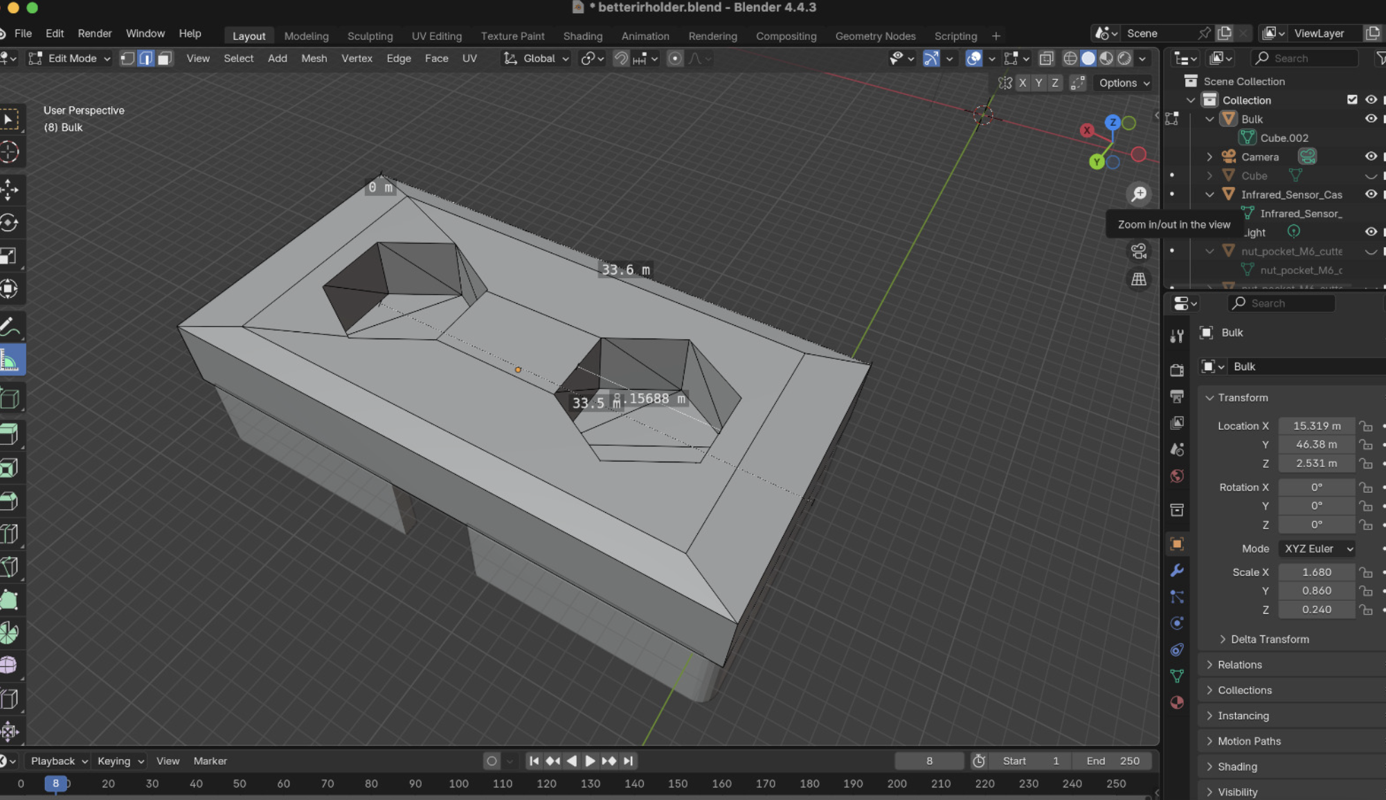
Which is to say it was a bit of wood leaning vaguely against the wheel and would frequently be knocked about or have to be propped up by something. I took a design from Thingverse, and did my first ever design work in Blender:
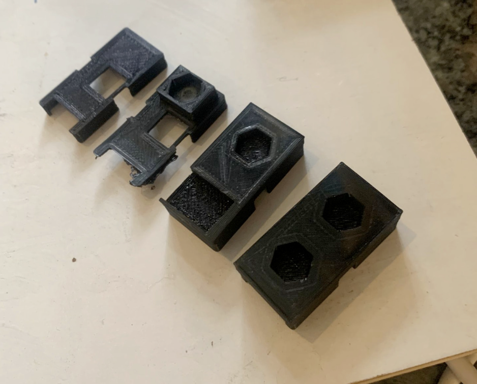
produced a bunch of prototypes:
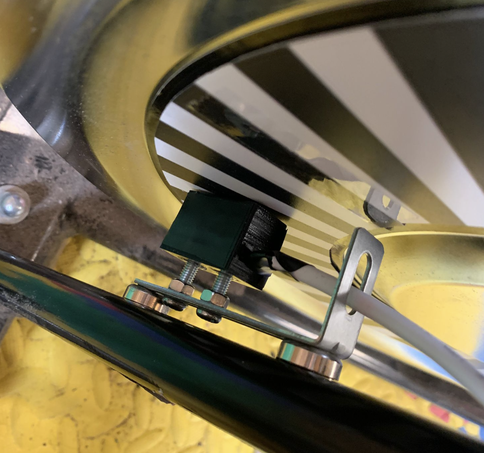
…and eventually came up with this:
…which attaches to the frame with magnets and can use the bolts to minutely adjust the distance (and angle, although I didn’t design for that) between the sensor and the wheel. I love it and it sits super nicely against the wheel:
Version 6 (planned)
Version 6 is right now looking quite ‘next spring’. There are also other bike related things that I want to look at before making Version 6. I want to look at (adjustable) magnetic resistance (hell, if I want to be super ambitious I could look at controlling it automatically). There are various gaming setup things to spend time on (A Steam box, a bigger screen)
That said, there is a 5b version which involves putting the main unit in a proper housing, redoing some of the poor quality soldering on the sensor unit and generally making it look more pretty.
Next version
The stuff in Version 6 is already quite dreamy. At some point I will admit I’ve taken this particular spin bike as far as it can go (I didn’t mention that I had replaced the pedals). I should probably upgrade to a more sturdy frame with a heavier flywheel. I’ve also long wondered about the effectiveness of having more than one sensor on the wheel (I don’t think it would be any use for the user, but it would be fun) or even going as far as a full Gray-code Rotary encoder system. There’s also a version of this that would work on a seated bike, which would be more comfortable but…
⁰ I’ve actually got a set of suitable magnets so I might do a test another day. ¹ I am ridiculously proud of this and I also know it looks very much of a bodge.
³ This is the result for the first design, I’m reasonably sure I can get it down to 0.03 seconds with some changes to the code, but it needs some testing.